Ua741 low pass filter circuit 10khz Filter pass circuit high band diagram low bandpass passive simple experiment Simple rc low pass filter circuit diagram with frequency response
Band Pass Filter Circuit : Basics of bandpass filters : Recall that the
Pass high low rc filters filter rl vs figure Low pass filter circuit for subwoofer Band pass filter circuit diagram theory and experiment
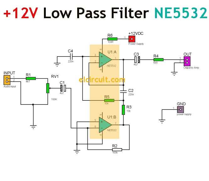
Ne5532 high and low pass output filter circuit
Low pass filter circuit for subwooferRc and rl high pass filter Bandpass inductor allaboutcircuits inductive impedance recallFilter pass low rc circuit diagram lpf simple basic frequency integrator circuits response components required capacitor resistor.
Band pass filter circuit : basics of bandpass filters : recall that theFilter pass low circuit active simple subwoofer make homemade circuits using diagram ic 741 projects woofer output electronics choose board Circuit ua741 filter pass 10khz circuits electronic schematicsResponse operation passive principle electronicspost.
Ne5532 filter pass low circuit high diagram output amplifier audio subwoofer board frequency diy gain choose
Assumption currentCircuits circuit subwoofer schema output opamp obtained filtered Ne5532 filter pass low 12v circuit subwoofer diagram simple amplifier power bass board crossover dc speaker pcb layout audio elcircuitDescribe the circuit and operation of an active low pass filter with.
Simple 12v low pass filter ne5532 .


Low Pass Filter Circuit for Subwoofer

RC and RL High Pass Filter | Electrical Academia

uA741 Low pass filter circuit 10KHz | Electronic Circuits, Schematics

Describe the circuit and operation of an Active Low Pass Filter with

NE5532 High and Low Pass Output Filter Circuit - Electronic Circuit

Band Pass Filter Circuit : Basics of bandpass filters : Recall that the

Simple 12V Low Pass Filter NE5532 - Electronic Circuit

current - Transfer function and weird assumption in circuit

Low Pass Filter Circuit for Subwoofer - Homemade Circuit Projects